Lifecycle service boundary

Kardex Uptime Plan begins with failure ownership

Define the equipment boundary, service clock, access conditions, spare strategy and return-to-service evidence before system availability becomes a contractual metric. Documented capacity, safety inputs and recovery planning stay visible from RFQ through SAT.

Review the Boundary
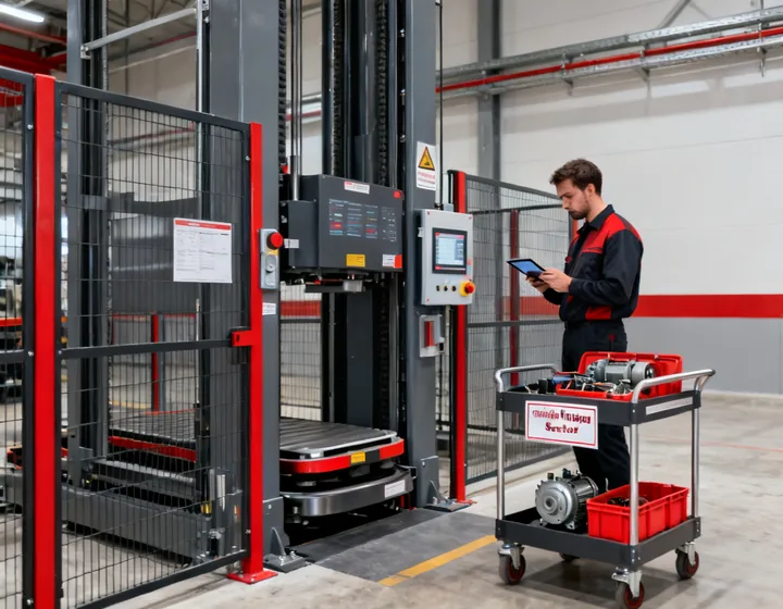
Warehouse storage maintenance readiness inspection for Kardex systems
Availability definition

Use one clock and one event classification

System availability is calculated only after the measured boundary is named. The record identifies included subsystems, the observation window and whether planned maintenance, lack of upstream work, downstream blockage, utilities or operator delay are excluded.

For a vertical storage installation, subsystem and end-to-end values may differ. A vertical lift module can be available while the upstream tote check rejects loads; conversely, a WCS can issue valid commands while a mechanical bay remains isolated. Mean time to repair depends on diagnosis, safe access and spare readiness—not travel time alone.

Measured boundary

Tray-served bay, shuttle lane, transfer conveyor, controls and named interfaces.

Observation window

Shift calendar, planned stops and the timestamp source used across equipment logs.

Event ownership

WMS decision, WCS orchestration, PLC execution, facility utility or operating action.

Restoration proof

Safe reset, test cycle, load disposition and event closure accepted by the site team.

Recovery scenarios

Rehearse conditions that stop tray flow

Scenario A

Blocked storage location

A location sensor or inventory mismatch prevents putaway. The plan states who validates physical occupancy, how the WMS/WCS record is reconciled, where the tray or tote waits and which test proves the location is ready again.

Scenario B

Load outside the permitted envelope

A damaged tote, leaning stack or excessive overhang is rejected before entry. Recovery requires a safe removal route and quarantine disposition; bypassing the check is not treated as a routine operating shortcut.

Scenario C

Bay equipment fault

The isolated zone, trapped material and remaining serviceable capacity are identified. Peak rate versus operational resilience is explicit: temporary capacity reduction may be preferred over an unsafe bypass.

Practical limitations

  • Remote support cannot replace on-site access where guarding must be opened or a load must be stabilized.
  • A target response time does not equal restoration time when site permits, specialist lifting or unavailable spares control the path.
  • Availability targets do not remove the need for planned inspection, tray damage reporting and operator training.
Spares and response

Stock by failure exposure, not by part count

A critical-spares matrix links each item to installed quantity, failure effect, diagnostic confidence, lead time, shelf-life or storage condition, replacement competence and commissioning step. It distinguishes consumables from parts that can stop a bay or remove the system’s redundancy.

ClassTypical basisReadiness evidence
Site stockHigh consequence or long replenishment lead timeLabeled location, preservation check and compatible revision
Regional stockShared component with predictable transport routeDispatch owner, cutoff time and customs boundary
Repairable assemblySpecialist rebuild and controlled exchangeReturn authorization, test method and configuration record

Response clock checkpoints

  1. 0: site logs asset, alarm, state and impact
  2. 1: support confirms ownership and safe diagnostic path
  3. 2: parts, access and personnel route are agreed
  4. 3: repair is verified with a defined test load
  5. 4: event record closes with root cause and action
Readiness evidence

Connect each commitment to a document and a test

Request an Uptime Review
FAT

Factory-representable functions, simulated interfaces and open deviations listed.

Map the test scope
SAT

Installed geometry, safety chain, site interfaces and recovery scenarios witnessed.

Define acceptance